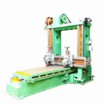
What is the Quick Return Mechanism?
The quick return mechanism is a mechanical linkage that
converts rotational motion into reciprocating motion, with the returning stroke
being faster than the forward stroke. It is commonly used in machines such as
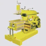
shapers, slotters, and some types of presses, where a rapid return stroke is
required to increase productivity.
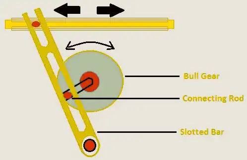
The basic principle of the quick return mechanism is that a
rotating crank is used to drive a connecting rod, which is then used -to drive
a sliding ram or tool. However, instead of the crank being mounted directly on
the main shaft, it is offset to create a varying eccentricity. This means that
during the forward stroke, the ram moves slowly, while during the return
stroke, the ram moves rapidly due to the increased eccentricity of the crank.
The quick return mechanism allows for the efficient shaping
of materials such as metal or wood, as the rapid return stroke ensures that the
tool or cutter is quickly repositioned for the next cutting operation.
Additionally, it can be used to create complex shapes and profiles by varying
the shape of the cutter or tool and the path of the sliding ram.
Types of Quick Return Mechanism:
There are several types of quick return mechanisms, each
with its own advantages and disadvantages. Here are some common types:
- Whitworth
Quick Return Mechanism: This is the simplest type of quick return
mechanism, and it consists of a crankshaft with an eccentric and a
connecting rod that drives a sliding block. During the forward stroke, the
sliding block moves slowly, while during the return stroke, it moves
rapidly due to the increased eccentricity of the crank. - Crank
and Slotted Lever Mechanism: This mechanism uses a crankshaft with an
eccentric to drive a slotted lever, which in turn drives a connecting rod
and a sliding ram or tool. The length of the slot in the lever determines
the stroke length and the speed of the return stroke. - Whitworth-Diagram
Mechanism: This mechanism uses two crankshafts with eccentrics and
connecting rods that drive a parallelogram linkage. During the forward
stroke, the linkage moves slowly, while during the return stroke, it moves
rapidly due to the changing orientation of the parallelogram. - Hydraulic
Quick Return Mechanism: This mechanism uses hydraulic cylinders to control
the movement of the ram or tool, with a control valve that regulates the
flow of hydraulic fluid. By adjusting the valve, the speed and stroke
length of the ram can be varied. - Scotch
Yoke Mechanism: This mechanism uses a rotating disk with a slot that
drives a sliding block or yoke, which in turn drives a connecting rod and
a sliding ram or tool. During the forward stroke, the yoke moves slowly,
while during the return stroke, it moves rapidly due to the shape of the
slot in the disk.
Each of these types of quick return mechanisms has its own
advantages and limitations, depending on the specific application and
requirements.
Components of a Quick Return Mechanism
The components of a quick return mechanism may vary
depending on the specific design and application, but typically include the
following:
- Crankshaft:
The crankshaft is the primary rotating component of the mechanism, which
converts rotary motion into reciprocating motion. - Eccentric:
The eccentric is an off-center component attached to the crankshaft, which
provides the variable distance or throw necessary for the reciprocating
motion. - Connecting
Rod: The connecting rod connects the eccentric to the sliding block or
other reciprocating component, transmitting the motion from the
crankshaft. - Sliding
Block: The sliding block is the component that moves back and forth in
response to the motion of the connecting rod and eccentric, providing the
reciprocating motion necessary for the machine or tool. - Flywheel:
The flywheel is a rotating mass that helps to smooth out the motion of the
mechanism, providing a more constant and consistent output. - Bearings:
Bearings are used to support the rotating components of the mechanism,
reducing friction and wear. - Control
Mechanisms: Control mechanisms, such as hydraulic valves or electronic
controllers, may be used to regulate the speed and stroke length of the
mechanism, or to control other parameters such as force or pressure.
Overall, the specific components of a quick return mechanism
will depend on the specific application and requirements, but the above
components are typically present in most designs.
Working principle of Quick Return Mechanism
The working principle of a quick return mechanism involves
converting rotary motion into reciprocating motion using a crankshaft and
eccentric. The crankshaft rotates, driven by a motor or other power source, and
the eccentric is mounted off-center on the crankshaft. As the crankshaft
rotates, the eccentric moves in a circular path, transmitting motion to the
connecting rod.
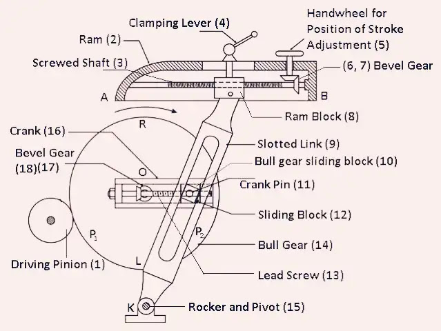
The connecting rod is connected to a sliding block or other
reciprocating component, which moves back and forth in response to the motion
of the eccentric. The distance or throw of the reciprocating motion is
determined by the distance between the center of the crankshaft and the center
of the eccentric. This distance is variable and can be adjusted to control the
stroke length of the mechanism.
The quick return mechanism is designed to provide a faster
return stroke than the forward stroke, which allows for more efficient cutting
or forming operations. This is achieved by designing the mechanism so that the
distance between the center of the crankshaft and the center of the eccentric
is shorter on the return stroke than on the forward stroke. This causes the
sliding block to move more quickly on the return stroke, allowing for faster
processing and increased productivity.
Overall, the working principle of the quick return mechanism
involves converting rotary motion into reciprocating motion and controlling the
stroke length and speed of the reciprocating motion to achieve faster, more
efficient processing of materials or other operations.
Applications of Quick Return Mechanism:
The quick return mechanism is commonly used in a variety of
machines and applications that require fast and efficient reciprocating motion.
Some common applications include:
- Shaping
Machines: The quick return mechanism is commonly used in shaping machines
to move the cutting tool back and forth rapidly, allowing for efficient
shaping of metal, wood, or other materials. - Slotting
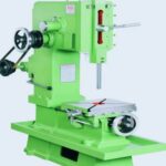
Machines: Slotting machines use the quick return mechanism to move a
slotted cutting tool up and down rapidly, allowing for precise and
efficient cutting of slots and other shapes in metal or other materials. - Presses:
Mechanical presses use the quick return mechanism to rapidly move the ram
up and down, allowing for efficient stamping, punching, and other forming
operations. - Shearing
Machines: Shearing machines use the quick return mechanism to move a blade
rapidly back and forth, allowing for efficient cutting of metal or other
materials. - Saws:
Some types of saws use the quick return mechanism to move the saw blade up
and down rapidly, allowing for efficient cutting of wood, metal, or other
materials.
Overall, the quick return mechanism is widely used in
manufacturing, machining, and other industrial applications where fast and
efficient reciprocating motion is required.
Advantages and Disadvantages of Quick Return Mechanism:
Advantages of Quick Return Mechanism:
- High
Productivity: The main advantage of the quick return mechanism is that it
enables high productivity due to the rapid return stroke. This allows for
more efficient cutting or forming operations, which can result in faster
production rates and increased output. - Precision:
The quick return mechanism can be designed to provide precise control over
the stroke length and speed, which can result in higher accuracy and
better quality finished products. - Versatility:
The mechanism can be used in a variety of machines and applications,
making it a versatile option for manufacturers and other industrial users. - Reduced
Operator Fatigue: The use of quick return mechanism reduces the operator’s
fatigue, making it more convenient to work on the machine.
Disadvantages of Quick Return Mechanism:
- High
Initial Cost: The cost of designing and implementing a quick return
mechanism can be higher than that of other types of mechanisms due to its
complexity. - Increased
Maintenance: The mechanism may require more frequent maintenance due to
the higher speeds and forces involved, which can increase maintenance
costs and downtime. - Limited
Stroke Length: The quick return mechanism is typically limited in the
length of the stroke that can be achieved, which can be a disadvantage in
certain applications. - Noise
and Vibration: The rapid movement of the mechanism can generate high
levels of noise and vibration, which can be a concern in certain work
environments. - Safety
Hazards: The high speeds and forces involved in the quick return mechanism
can pose safety hazards if not properly designed, operated, and
maintained.
Quick Return Mechanism Calculations
The calculations involved in designing a quick return
mechanism will depend on the specific application and requirements. However,
some common calculations include:
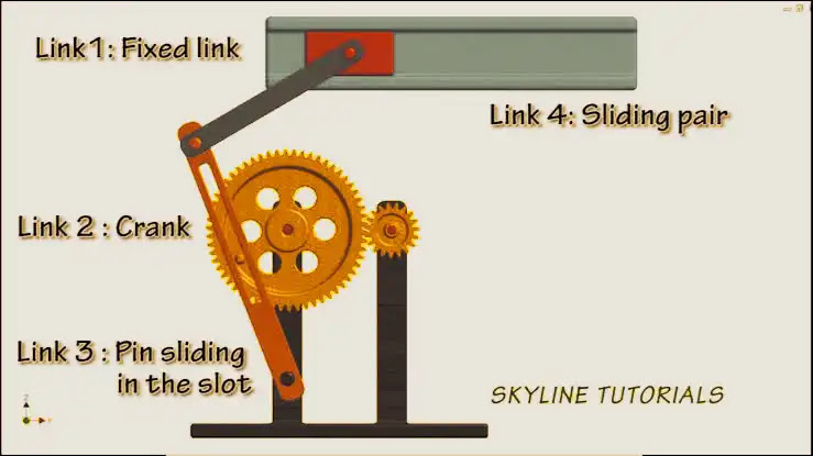
- Stroke
Length: The stroke length of the mechanism is determined by the distance
between the center of the crankshaft and the center of the eccentric. This
distance can be calculated based on the desired stroke length and the
dimensions of the mechanism. - Velocity
Ratio: The velocity ratio of the mechanism is the ratio of the velocity of
the cutting tool or other working component to the velocity of the sliding
block. It is typically calculated using the formula VR = (1 + r)/(1 – r),
where r is the distance between the center of the crankshaft and the
center of the eccentric, divided by the length of the connecting rod. - Cutting
Speed: The cutting speed of the tool or other working component is
calculated based on the surface speed of the workpiece and the desired
feed rate. - Feed
Rate: The feed rate of the tool or other working component is calculated
based on the cutting speed and the desired depth of cut or material
removal rate. - Power
Requirements: The power requirements of the mechanism are calculated based
on the force required to perform the cutting or forming operation, the
velocity of the working component, and other factors such as friction and
efficiency.
Overall, the calculations involved in designing a quick
return mechanism can be complex and will depend on the specific requirements of
the application. It is important to carefully consider factors such as stroke
length, velocity ratio, cutting speed, and power requirements to ensure that
the mechanism will provide the desired performance and productivity.
How to make Quick Return Mechanism
The process of making a quick return mechanism will depend
on the specific design and requirements, but some general steps to follow are:
- Determine
the design specifications: Before starting the construction process,
determine the specific design requirements for your quick return mechanism.
This will include factors such as the desired stroke length, velocity
ratio, cutting speed, and power requirements. - Select
the materials: Choose materials that are strong, durable, and able to
withstand the forces and stresses of the mechanism. Common materials for
the crankshaft, connecting rod, and eccentric include steel or aluminum. - Fabricate
the crankshaft and eccentric: Use a lathe or other metalworking tools to
create the crankshaft and eccentric. The crankshaft should be machined to
a smooth finish, with a precise center hole and appropriately sized
journal bearings. The eccentric should be mounted off-center on the
crankshaft, with the distance between the center of the crankshaft and the
center of the eccentric determined based on the desired stroke length. - Fabricate
the connecting rod: The connecting rod should be machined to the
appropriate length and shape, with a hole at each end for mounting to the
eccentric and sliding block. - Fabricate
the sliding block: The sliding block should be machined to the desired
shape and size, with holes at each end for mounting the connecting rod. - Assemble
the mechanism: Assemble the crankshaft, eccentric, connecting rod, and
sliding block according to the design specifications. Use appropriate
bearings or bushings to reduce friction and wear. - Test
and adjust: Once the mechanism is assembled, test it to ensure that it
functions properly and meets the desired design specifications. Adjust as
necessary to optimize performance.
Overall, the process of making a quick return mechanism
requires careful planning, precise machining, and testing to ensure that it
functions properly and provides the desired performance.
Whitworth Quick Return Mechanism
The Whitworth Quick Return Mechanism is a type of quick
return mechanism named after its inventor, Sir Joseph Whitworth. It is a
modification of the basic slider-crank mechanism and is commonly used in
shaping and cutting machines.
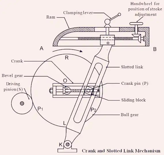
The Whitworth Quick Return Mechanism is similar to a basic
slider-crank mechanism, with the addition of an intermediate link between the
connecting rod and the slide. The intermediate link is connected to the slide
at one end and to the connecting rod at the other end. The crankshaft and
eccentric are mounted on the same axis, with the eccentric offset from the
centerline of the crankshaft. As the crankshaft rotates, the eccentric imparts
a reciprocating motion to the intermediate link, which in turn causes the slide
to move in a quick return motion.
The Whitworth Quick Return Mechanism provides a faster
cutting or shaping stroke and a slower return stroke, which improves the
efficiency and productivity of the machine. It also reduces the shock and
vibration of the mechanism, which can improve the quality of the workpiece.
However, the Whitworth Quick Return Mechanism can be more
complex and difficult to manufacture than other types of quick return
mechanisms. It also requires careful adjustment and maintenance to ensure that
it operates smoothly and reliably.