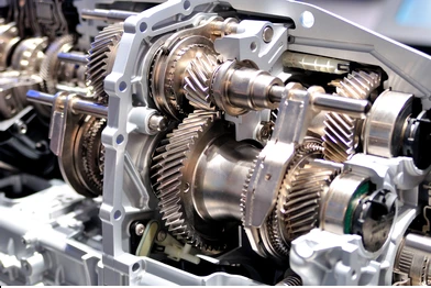
What is Gear?
In general, the term “gear” refers to a mechanical
component consisting of toothed wheels or cylinders that transmit rotational
motion and torque between two or more components. Gears are commonly used in
machinery, vehicles, and other mechanical devices to transfer power and change
the speed, direction, or torque of a rotating shaft.

Gears come in a variety of shapes, sizes, and configurations
depending on their intended application. Some common types of gears include
spur gears, bevel gears, helical gears, worm gears, and rack and pinion gears.
Each type of gear has its own unique characteristics and is used in specific
situations.
Gears are critical components in many mechanical systems and
are used in a wide range of applications, from simple machines such as bicycles
to complex industrial equipment such as turbines and gearboxes.
How many types of Gears and what are they?
There are several types of gears, and they can be classified
based on various factors, including their shape, orientation, size, and
application. Here are some of the most common types of gears:
- Spur
Gears: Spur gears are the most common type of gears, and they have
straight teeth that run parallel to the gear’s axis. They are used in
applications where power transmission between parallel shafts is required. - Helical
Gears: Helical gears are similar to spur gears, but their teeth are
angled, which causes them to run more smoothly and quietly. They are
commonly used in high-speed applications. - Bevel
Gears: Bevel gears have cone-shaped teeth and are used to transmit power
between intersecting shafts. - Worm
Gears: Worm gears are used to transmit power between non-parallel shafts.
They consist of a worm and a worm wheel, and the gear ratio is determined
by the number of teeth on each component. - Planetary
Gears: Planetary gears, also known as epicyclic gears, consist of a
central sun gear, planet gears, and an outer ring gear. They are used in
applications where high torque is required. - Rack
and Pinion Gears: Rack and pinion gears are used to convert rotary motion
into linear motion. They consist of a straight bar (rack) and a gear with
teeth (pinion). - Spiral
Bevel Gears: Spiral bevel gears are similar to bevel gears, but their
teeth are angled in a spiral pattern, which reduces noise and vibration. - Hypoid
Gears: Hypoid gears are a type of spiral bevel gear, but their pinion and
ring gear axes are offset, which allows for higher gear ratios and torque
capacity.
These are just some of the most common types of gears, and
there are many other variations and configurations depending on the
application.
Introduction to different types of Gears
Gears are mechanical components that transmit power and
motion between rotating shafts. There are several types of gears, each with its
own unique properties and applications. Here’s a brief introduction to some of
the most common types of gears:
- Spur
Gears: Spur gears are the most common type of gears and have straight
teeth that run parallel to the axis of the gear. They are used for power
transmission between parallel shafts and are typically used in low- to
medium-speed applications. - Helical
Gears: Helical gears have teeth that are angled in a spiral pattern, which
allows for smoother and quieter operation than spur gears. They are
commonly used in high-speed applications and can transmit power between
parallel or non-parallel shafts. - Bevel
Gears: Bevel gears have cone-shaped teeth and are used to transmit power
between intersecting shafts. They are commonly used in differential gears
in automobiles and other machinery. - Worm
Gears: Worm gears consist of a worm and a worm wheel and are used to
transmit power between non-parallel shafts. They provide high gear
reduction and are often used in applications where space is limited. - Planetary
Gears: Planetary gears, also known as epicyclic gears, are made up of a
central sun gear, planet gears, and an outer ring gear. They are used in
applications where high torque and compact size are required. - Rack
and Pinion Gears: Rack and pinion gears are used to convert rotary motion
into linear motion. They consist of a straight bar (rack) and a gear with
teeth (pinion) and are commonly used in steering systems and linear motion
applications. - Spiral
Bevel Gears: Spiral bevel gears are similar to bevel gears, but their
teeth are angled in a spiral pattern. They are used in applications where
smooth and quiet operation is required, such as in automobile
differentials. - Hypoid
Gears: Hypoid gears are a type of spiral bevel gear, but their pinion and
ring gear axes are offset, which allows for higher gear ratios and torque
capacity. They are commonly used in heavy-duty applications such as in
trucks and construction equipment.
These are just a few examples of the many types of gears
available, and each has its own unique advantages and disadvantages. Choosing
the right type of gear for a given application requires careful consideration
of factors such as load, speed, torque, and space limitations.
Gear making Materials
Gears can be made from a wide range of materials, depending
on the specific application and requirements. Here are some of the most common
materials used in gear making:
- Steel:
Steel is a common material used in gear making due to its strength,
durability, and resistance to wear and corrosion. It is often alloyed with
other metals to enhance its properties. - Cast
Iron: Cast iron is another common material used in gear making, especially
for low-speed and low-power applications. It is easy to machine and has good
wear resistance, but it is brittle and can crack under heavy loads. - Brass:
Brass is a non-ferrous metal that is commonly used for gears in low-power
and low-speed applications. It has good corrosion resistance and is easy
to machine. - Bronze:
Bronze is a copper alloy that is often used for gears in high-load and
high-speed applications. It has good wear resistance and is able to
withstand heavy loads without deforming. - Plastic:
Plastic gears are commonly used in applications where low noise, low
weight, and low cost are important factors. They can be made from a
variety of materials, including nylon, acetal, and polycarbonate. - Aluminum:
Aluminum gears are lightweight and have good corrosion resistance, but
they are not as strong as steel or bronze gears. They are commonly used in
low-load and low-speed applications. - Titanium:
Titanium is a lightweight and strong metal that is often used in
high-performance gear applications, such as in aerospace and military
equipment. It has good corrosion resistance and is able to withstand high
temperatures and heavy loads.
These are just some of the most common materials used in
gear making, and there are many other materials that may be used depending on
the specific requirements of the application.
Failure of Gear teeth because
Gear teeth can fail due to a variety of reasons, including:
- Wear:
Over time, the repeated contact between gear teeth can cause them to wear
down, which can result in poor meshing and reduced efficiency. Wear can be
caused by factors such as inadequate lubrication, contaminants in the
lubricant, or poor surface finish. - Fatigue:
Fatigue failure occurs when a gear tooth fails due to repeated stress
cycles, even if the stress is below the gear’s ultimate strength. This can
occur due to factors such as overloading, shock loading, or inadequate
design. - Tooth
Breakage: Tooth breakage can occur when a gear tooth is subjected to a
sudden and excessive load. This can happen due to factors such as
inadequate design, material defects, or insufficient hardness. - Surface
Pitting: Surface pitting is a type of wear that appears as small pits or
craters on the surface of the gear teeth. It can be caused by factors such
as inadequate lubrication, contaminants in the lubricant, or poor surface
finish. - Scoring:
Scoring occurs when metal is torn away from the surface of the gear teeth
due to friction. It can be caused by factors such as inadequate
lubrication, excessive loading, or poor surface finish. - Corrosion:
Corrosion can cause damage to gear teeth by weakening the surface of the
metal. It can be caused by factors such as exposure to moisture,
saltwater, or other corrosive substances. - Overheating:
Overheating can cause gear teeth to fail by altering the material
properties of the gear, such as its hardness and toughness. It can be
caused by factors such as inadequate lubrication, excessive loading, or
high operating temperatures.
These are just some of the most common causes of gear tooth
failure, and each can have a significant impact on the performance and
reliability of the gear system. Proper design, materials selection, and
maintenance can help reduce the risk of gear tooth failure.
Name the different parts of the Gear
Here are the different parts of a gear:
- Teeth:
The teeth are the raised portions on the outer circumference of the gear
that mesh with the teeth of another gear. The shape, size, and number of
teeth can vary depending on the gear’s application and design. - Face:
The face is the surface of the gear that is perpendicular to the axis. It
can be flat or curved, depending on the gear’s design. - Flank:
The flank is the surface of the gear that connects the teeth to the face.
It can also be flat or curved, depending on the gear’s design. - Root:
The root is the base of the gear tooth where it meets the gear’s body. It
is the part of the gear tooth that is most susceptible to stress and
failure. - Pitch
Diameter: The pitch diameter is the diameter of the imaginary circle that
the gear teeth would form if they were to mesh perfectly with the teeth of
another gear. It is used to calculate the gear’s pitch, or the distance
between teeth. - Addendum:
The addendum is the distance between the pitch circle and the top of the
gear tooth. It is the part of the gear tooth that makes contact with the
teeth of another gear. - Dedendum:
The dedendum is the distance between the pitch circle and the bottom of
the gear tooth. It provides clearance for the teeth of another gear to
pass. - Pressure
Angle: The pressure angle is the angle between the tangent to the pitch
circle and the line of action of the force between two meshing gears. It
is an important parameter in gear design, as it affects the load-carrying
capacity and efficiency of the gear system. - Hub:
The hub is the central portion of the gear that is used to mount the gear
onto a shaft or other component.
These are the main parts of a gear, and understanding each
component is important in designing and selecting gears for specific applications.
Use of Gear
Gears are used in a wide range of mechanical devices and
systems to transmit power and motion between rotating shafts. They are used to
change the speed, torque, and direction of rotation of the driven shaft
relative to the driving shaft.
Some common applications of gears include:
- Automobile
transmissions: Gears are used in automobile transmissions to change the
speed and torque of the engine to the wheels. - Industrial
machinery: Gears are used in a variety of industrial machinery, such as
conveyor systems, cranes, and machine tools, to transmit power and motion
between components. - Power
tools: Gears are used in power tools such as drills and saws to transfer
power from the motor to the cutting or drilling blade. - Robotics:
Gears are used in robotics to transmit power and motion between the motor
and various joints and actuators. - Wind
turbines: Gears are used in wind turbines to transfer power from the rotor
to the generator. - Watches
and clocks: Gears are used in watches and clocks to transfer power and
motion between the mainspring and the hands. - Bicycles:
Gears are used in bicycles to allow the rider to adjust the speed and
torque of the pedals relative to the wheel.
These are just a few examples of the many applications of
gears, and their versatility and efficiency make them a crucial component in
many mechanical systems.
Types of Gear Teeth
There are several types of gear teeth used in gear design,
each with its own advantages and disadvantages. Some common types of gear teeth
include:
- Spur
Gear Teeth: Spur gear teeth are the simplest type of gear teeth, with
straight teeth that run parallel to the axis of the gear. They are easy to
manufacture and provide efficient power transmission, but they can be
noisy and generate high axial forces. - Helical
Gear Teeth: Helical gear teeth are similar to spur gear teeth, but they
are angled along the axis of the gear, which makes them quieter and
smoother running. However, they can be more difficult to manufacture and
require more axial space. - Bevel
Gear Teeth: Bevel gear teeth are used in bevel gears, which are gears with
angled teeth that intersect at the gear’s axis. They are used to transmit
power between shafts that are at an angle to each other. Bevel gear teeth
can be straight or curved, depending on the gear’s design. - Spiral
Gear Teeth: Spiral gear teeth are similar to helical gear teeth, but they
have a curved shape that makes them even quieter and smoother running.
However, they can be more difficult to manufacture and require more axial
space. - Worm
Gear Teeth: Worm gear teeth are used in worm gears, which are gears with a
helical gear wrapped around a central shaft. They are used to transmit
power between shafts that are at a right angle to each other. Worm gear
teeth have a unique shape that allows for high gear reduction ratios, but
they can be less efficient than other types of gears. - Hypoid
Gear Teeth: Hypoid gear teeth are used in hypoid gears, which are gears
with an offset shaft that allows for power transmission between shafts
that are not parallel. Hypoid gear teeth have a curved shape that allows
for smoother operation and high torque transmission, but they can be more
difficult to manufacture.
These are just a few examples of the many types of gear
teeth used in gear design, and each type has its own unique advantages and
disadvantages depending on the gear’s application and operating conditions.
Read More: What is the gear box? How many types of gear box and what is it? Detailed discussion about gear box