A Pelton turbine is a type of hydraulic turbine used in
hydroelectric power generation. It was invented by American engineer Lester
Allan Pelton in the 1870s.
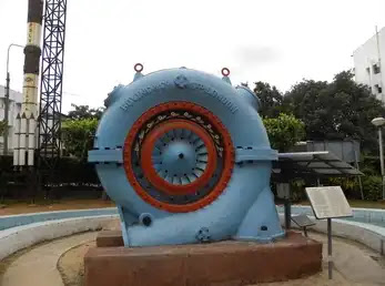
The Pelton turbine is designed to convert the kinetic energy
of a high-pressure water jet into mechanical energy that can be used to
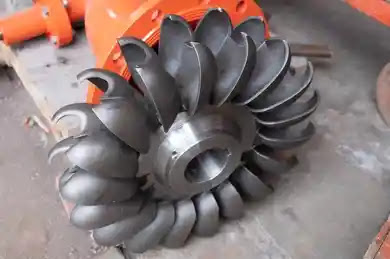
generate electricity. The turbine consists of a set of spoon-shaped buckets
arranged around the rim of a wheel, called a runner. The water jet is directed
onto the buckets, causing the runner to rotate.
The buckets are designed so that the water jet splits into
two parts, with each part passing on either side of the bucket. This creates a
force that drives the runner, as the water jet pushes against the curved
surface of the bucket. The buckets are shaped so that the water is discharged
tangentially, which increases the efficiency of the turbine.
Pelton turbines are particularly well-suited to high head,
low flow applications, where the water supply is under high pressure. They are
commonly used in mountainous regions where there is a lot of elevation change,
such as in the Western United States, Canada, and New Zealand.
Different parts of Pelton Turbine:
The main parts of a Pelton turbine include:
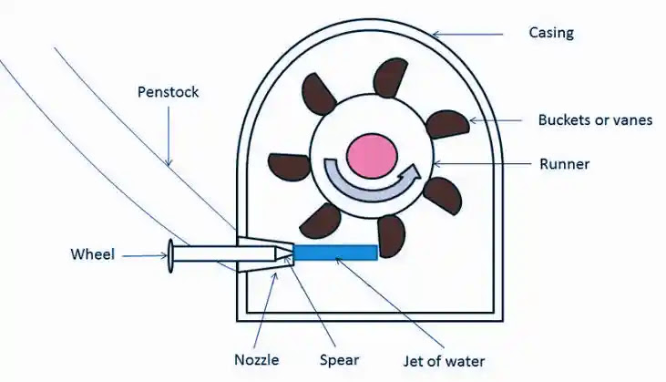
Nozzle:
This is the part of the turbine that directs the high-pressure water jet
onto the buckets of the turbine. The nozzle is designed to shape and
control the flow of water to maximize the efficiency of the turbine.
Runner:
The runner is the rotating part of the turbine that contains the bucket
assembly. It is typically made of a high-strength material, such as
stainless steel or titanium, to withstand the high rotational speeds and
the impact of the water jet.
Buckets:
The buckets are the spoon-shaped structures that are mounted on the runner.
They are designed to capture the water jet and split it into two parts,
deflecting the water at an angle that maximizes the transfer of kinetic
energy to the runner.
Shaft:
The shaft is the part of the turbine that connects the runner to the
generator. It transmits the mechanical energy produced by the runner to
the generator to produce electricity.
Bearings:
The bearings support the shaft and allow it to rotate freely. They are
typically made of high-strength materials, such as bronze or babbitt, and
are lubricated to reduce friction and wear.
Governor:
The governor is a control system that regulates the flow of water to the
turbine to maintain a constant rotational speed, even when the water
supply fluctuates. It is typically a mechanical or electronic system that
adjusts the flow of water through the nozzle based on the rotational speed
of the turbine.
Casing:
The casing is the outer shell of the turbine that contains the runner and
other components. It is designed to direct the flow of water to the nozzle
and prevent water from escaping outside of the turbine.
Working principle of Pelton Turbine:
The working principle of a Pelton turbine is based on the
conversion of kinetic energy of a high-velocity water jet into mechanical energy
that can be used to generate electricity. Here are the steps involved in the
working of a Pelton turbine:
High-pressure
water is directed through a nozzle, which converts the potential energy of
the water into kinetic energy by accelerating the water to a very high
velocity.
The
high-velocity water jet is then directed onto the buckets, which are
mounted on the rim of a wheel called the runner. The buckets are designed
in such a way that the water jet is split into two parts as it strikes the
buckets, and is deflected at an angle of 165 degrees. The angle of
deflection is designed to maximize the transfer of kinetic energy from the
water to the runner.
The
impact of the water on the buckets causes the runner to rotate. The
rotational speed of the runner depends on the velocity of the water jet
and the number of buckets on the runner.
The
rotating runner is connected to a shaft, which transmits the mechanical
energy produced by the turbine to a generator. The generator converts the
mechanical energy into electrical energy.
The
governor system monitors the rotational speed of the turbine and adjusts
the flow of water through the nozzle to maintain a constant speed.
After
passing through the buckets, the water is discharged from the turbine and
is usually returned to the river or a reservoir for further use.
Pelton turbines are highly efficient, especially in high
head, low flow applications, and are commonly used in hydroelectric power
generation.
Advantages and Disadvantages of Pelton Turbine:
Advantages of Pelton Turbine:
Highly
efficient: Pelton turbines are highly efficient, especially in high head,
low flow applications, and can achieve efficiencies of up to 95 percent.
Low
maintenance: Pelton turbines have a simple design and are made of durable
materials, which makes them relatively easy to maintain and repair.
Suitable
for high head applications: Pelton turbines are best suited for high head
applications where the water supply is under high pressure, such as in
mountainous regions with a lot of elevation change.
Environmentally
friendly: Pelton turbines do not produce any harmful emissions or waste
products, making them an environmentally friendly option for power
generation.
Disadvantages of Pelton Turbine:
Limited
flow rate: Pelton turbines have a limited flow rate and are not well
suited for high flow applications.
High
initial cost: Pelton turbines have a high initial cost due to the complex
design and the materials used in their construction.
Dependence
on water supply: Pelton turbines rely on a consistent and reliable supply
of high-pressure water, which may not always be available.
Limited
range of applications: Pelton turbines are not suitable for all types of
hydroelectric power generation applications and are best suited for high
head, low flow situations.
Types of Pelton Turbine:
There are mainly two types of Pelton turbine based on the
number of nozzles used to supply water to the turbine:
Single
Nozzle Pelton Turbine: In a single nozzle Pelton turbine, a single nozzle
is used to supply water to the turbine. This type of turbine is suitable
for small-scale power generation and is commonly used in off-grid
applications.
Multi-Nozzle
Pelton Turbine: In a multi-nozzle Pelton turbine, multiple nozzles are
used to supply water to the turbine. This type of turbine is suitable for
larger-scale power generation and can generate a higher output of
electricity. Multi-nozzle Pelton turbines are commonly used in
hydroelectric power plants.
Pelton turbines can also be classified based on the number
of buckets on the runner. The most common types of Pelton turbines based on the
number of buckets are:
Single
bucket Pelton turbine: In a single bucket Pelton turbine, the runner has
only one bucket. This type of turbine is simple in design and is suitable
for small-scale power generation.
Double
bucket Pelton turbine: In a double bucket Pelton turbine, the runner has
two buckets. This type of turbine is more efficient than a single bucket
turbine and is suitable for medium-scale power generation.
Multi-bucket
Pelton turbine: In a multi-bucket Pelton turbine, the runner has multiple
buckets. This type of turbine is the most efficient and is suitable for
large-scale power generation.
Application of Pelton Turbine:
Pelton turbines are commonly used for hydroelectric power
generation in applications where there is a high head of water and low flow
rates. Some of the common applications of Pelton turbines are:
Hydroelectric
power plants: Pelton turbines are widely used in hydroelectric power
plants to generate electricity from water flowing through a dam. These
turbines are particularly suitable for high head applications.
Micro-hydro
power plants: Pelton turbines are also used in micro-hydro power plants to
generate electricity for off-grid applications. These small-scale systems
can be used to power remote homes, farms, and other small communities.
Pumped-storage
hydroelectricity: Pelton turbines are used in pumped-storage
hydroelectricity systems, where water is pumped from a lower reservoir to
a higher reservoir during times of low electricity demand, and then
released through the turbines to generate electricity during peak demand
periods.
Industrial
applications: Pelton turbines are also used in industrial applications,
such as in the mining industry, where they are used to power equipment and
machinery.
Water
treatment plants: Pelton turbines can be used in water treatment plants to
power pumps and other equipment used to treat and distribute water.
Overall, Pelton turbines are a reliable and efficient source
of clean energy, and their applications are well suited for areas with high
elevation change and limited flow rates.
Pelton Turbine Diagram
Pelton Turbine formula:
The basic formula for calculating the power output of a
Pelton turbine is:
P = (Q x H x η) / 1000
where:
P = Power output in kW
Q = Flow rate of water in
m^3/s
H = Head or pressure drop of water in meters
η = Efficiency of the
turbine (usually expressed as a percentage)
The formula for the velocity of the water jet in a Pelton
turbine is:
V = (2gh)^0.5
where:
V = Velocity of the water jet in m/s
g = Acceleration
due to gravity (9.81 m/s^2)
h = Head or pressure drop of water in meters
The formula for the force exerted by the water jet on the
bucket of a Pelton turbine is:
F = (Q x H) / (2 x g)
where:
F = Force exerted by the water jet on the bucket in N
Pelton turbine efficiency is the ratio of the actual power
output of the turbine to the theoretical power output that could be obtained if
all of the available energy in the water jet were converted into mechanical
energy by the turbine. The efficiency of a Pelton turbine depends on several
factors, such as the design of the turbine, the quality of the water supply,
and the operating conditions of the turbine.
The efficiency of a Pelton turbine is typically in the range
of 80-90%, although efficiencies of up to 95% can be achieved in some cases.
Factors that can affect the efficiency of a Pelton turbine include:
Head:
The efficiency of a Pelton turbine increases with the head of water
available, as this provides a greater potential energy difference between
the water before and after it passes through the turbine.
Nozzle
size: The efficiency of a Pelton turbine is also influenced by the size of
the nozzle, which controls the rate of flow of water through the turbine.
Bucket
design: The shape and design of the buckets on the turbine wheel can have
a significant impact on the efficiency of the turbine, as this affects the
amount of energy that can be extracted from the water jet.
Water
quality: The efficiency of a Pelton turbine can be affected by the quality
of the water supply, as impurities and debris in the water can reduce the
effectiveness of the turbine.
Overall, Pelton turbines are known for their high efficiency
and reliability, and are widely used for hydroelectric power generation in
applications where there is a high head of water and low flow rates.
আমি Md Shamim Hossain, TonBangla-এর প্রতিষ্ঠাতা। প্রযুক্তি, কম্পিউটার, প্রোগ্রামিং, প্রকৌশল ও শিক্ষামূলক বিষয় নিয়ে সহজ, তথ্যবহুল বাংলা কনটেন্ট তৈরি করি।