Venturi Meter Definition:
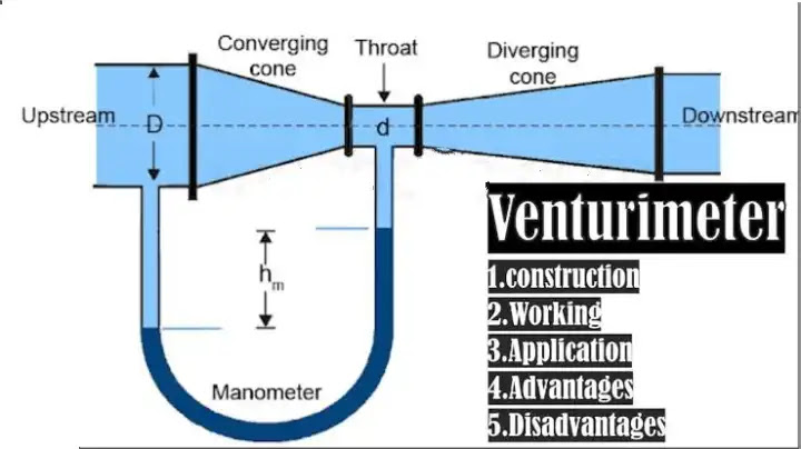
A venturi meter is a flow measurement device used to measure
the flow rate of a fluid in a pipe. It consists of a tapered tube with a
constriction in the middle, which causes the fluid to accelerate as it passes
through the constriction. The pressure difference created by the constriction
is measured using pressure taps located before and after the constriction. The
pressure difference is proportional to the square of the fluid velocity, and
therefore, the flow rate of the fluid can be calculated based on the pressure
difference and the dimensions of the venturi meter.
Venturi meters are commonly
used in various industries such as water supply systems, oil and gas pipelines,
and chemical processing plants.
Venturi Meter Parts
A venturi meter is a flow measurement device that typically
consists of the following parts:
- Inlet
section: This is the part of the venturi meter where the fluid enters. It
is designed to have a smooth, straight section that allows the fluid to
enter the venturi meter with minimal disturbance. - Converging
section: This is the section of the venturi meter where the tube narrows
down to form a constriction. The angle of the converging section is
carefully designed to minimize turbulence and maximize the acceleration of
the fluid as it passes through the constriction. - Throat:
The throat is the narrowest part of the venturi meter, where the fluid
velocity is at its maximum and the pressure is at its minimum. It is a
critical part of the venturi meter and is carefully designed to produce
accurate and reliable flow measurements. - Diverging
section: The diverging section is the part of the venturi meter where the
tube gradually widens back to its original diameter. The angle of the
diverging section is designed to minimize turbulence and allow the fluid
to return to its original velocity and pressure. - Pressure
taps: Pressure taps are small holes drilled into the venturi meter, one on
either side of the constriction. These taps allow pressure sensors to be
inserted into the venturi meter to measure the pressure difference created
by the constriction. - Flanges:
Flanges are used to attach the venturi meter to the pipe through which the
fluid is flowing. They are typically made of steel or other durable
materials and are designed to provide a tight seal between the venturi
meter and the pipe.
Overall, the design of a venturi meter is critical to its
accuracy and reliability as a flow measurement device. Careful attention must
be paid to the dimensions of each part of the meter to ensure that it operates
correctly and produces accurate measurements.
Working principle of Venturi meter
A venturi meter is a device used to measure the flow rate of
fluid in a pipe. It works on the principle of Bernoulli’s equation, which
states that as the velocity of a fluid increases, the pressure decreases, and
vice versa.

The venturi meter consists of a tube with a gradually
decreasing diameter, resulting in a constriction in the pipe. When fluid flows
through the pipe, it passes through the constriction, which increases the
velocity of the fluid and decreases the pressure. The pressure difference
between the two points before and after the constriction is measured to
calculate the flow rate of the fluid.
The working principle of the venturi meter can be explained
using Bernoulli’s equation. As fluid flows through the gradually decreasing
diameter of the tube, the velocity of the fluid increases, resulting in a
decrease in pressure. At the point of maximum constriction, the velocity of the
fluid is at its highest, and the pressure is at its lowest. As the fluid moves
beyond the constriction, the diameter of the tube gradually inc reases, and the velocity of the fluid
decreases, resulting in an increase in pressure.
The pressure difference created by the constriction in the
pipe is measured using pressure taps located before and after the constriction.
The pressure difference is proportional to the square of the velocity of the
fluid, and therefore, the flow rate of the fluid can be calculated based on the
pressure difference and the dimensions of the venturi meter.
In summary, the venturi meter works on the principle of
Bernoulli’s equation, where the pressure difference created by the constriction
in the pipe is used to calculate the flow rate of the fluid. The device is
commonly used in applications such as water supply systems, oil and gas pipelines,
and chemical processing plants.
Advantages and Disadvantages of Venturi Meter
Advantages of Venturi Meter:
- Accurate
measurement: Venturi meters offer high accuracy in measuring the flow of
fluids. The design of the venturi meter minimizes turbulence in the fluid
flow, resulting in more accurate measurements. - Low
pressure drop: The pressure drop across a venturi meter is relatively low
compared to other types of flow meters, such as orifice plates or flow
nozzles. This can result in energy savings in applications where the fluid
flow is at high pressure. - Wide
range of flow rates: Venturi meters can measure a wide range of flow
rates, making them suitable for use in a variety of applications. - Low
maintenance: Venturi meters are simple in design and have no moving parts,
making them easy to maintain and repair. - Resistant
to corrosion and erosion: Venturi meters are typically made of materials
that are resistant to corrosion and erosion, such as stainless steel or
plastic, which can extend their lifespan.
Disadvantages of Venturi Meter:
- High
cost: Venturi meters can be more expensive than other types of flow
meters, such as orifice plates or flow nozzles. - Large
size: Venturi meters can be relatively large in size, which can make them
difficult to install in some applications. - Flow
disturbance: The installation of a venturi meter can cause a flow
disturbance in the fluid, which can affect the accuracy of the
measurement. - Limited
application: Venturi meters may not be suitable for fluids that contain
solids or that are prone to clogging, as the design of the meter can
create areas where solids can accumulate.
Overall, the advantages of venturi meters in terms of
accuracy, low pressure drop, and wide range of flow rates make them a popular
choice for fluid flow measurement in many applications. However, the cost and
size of the meter, as well as potential flow disturbances and limitations in
certain applications, should be considered when selecting a flow meter for a
specific application.
Venturi Meter Specification:
The specifications of a venturi meter typically include the
following:
- Diameter:
The venturi meter is designed to fit a specific pipe diameter, which can
range from a few millimeters to several meters, depending on the
application. - Material:
The venturi meter is typically made of materials that are resistant to
corrosion and erosion, such as stainless steel or plastic. - Pressure
Rating: The venturi meter must be designed to withstand the maximum
pressure that will be encountered in the pipe. The pressure rating is
typically specified in pounds per square inch (psi) or kilopascals (kPa). - Flow
Range: The venturi meter must be designed to measure the expected range of
flow rates. The flow range is typically specified in cubic meters per hour
(m3/h) or gallons per minute (gpm). - Accuracy:
The accuracy of the venturi meter depends on the design and manufacturing
tolerances. The accuracy is typically specified as a percentage of the
actual flow rate. - Installation:
The venturi meter must be installed properly to ensure accurate flow measurement.
The installation specifications may include requirements for the upstream
and downstream piping, as well as the orientation and distance of the
meter from obstructions. - Calibration:
The venturi meter must be calibrated to ensure accurate flow measurement.
The calibration specifications may include requirements for the flow rate,
temperature, and pressure of the fluid.
Overall, the specifications of a venturi meter are critical
to its performance and accuracy in measuring fluid flow. The design and
manufacturing must take into account the specific application requirements to
ensure reliable and accurate measurement.
Applications of Venturi meter
Venturi meters are commonly used in a wide range of
applications for measuring the flow rate of fluids, including:
- Water
supply and treatment: Venturi meters are used to measure the flow rate of
water in water treatment plants, reservoirs, and distribution systems. - Chemical
and process industries: Venturi meters are used to measure the flow rate
of chemicals, gases, and other fluids in various industrial processes,
such as oil refining, petrochemicals, and food processing. - HVAC
systems: Venturi meters are used in heating, ventilation, and air
conditioning (HVAC) systems to measure the flow rate of air and other
fluids. - Aerospace:
Venturi meters are used in aircraft to measure the airspeed of the
aircraft. - Automobile
industry: Venturi meters are used in cars and other vehicles to measure
the air flow rate in the engine and to calculate fuel injection rates. - Marine
industry: Venturi meters are used in ships to measure the flow rate of
fluids, such as fuel oil, ballast water, and bilge water. - Agriculture:
Venturi meters are used in irrigation systems to measure the flow rate of
water in agricultural fields.
Overall, venturi meters are versatile instruments that are
widely used in many industries and applications for measuring fluid flow rates
accurately and reliably.
Difference between Venturi meter and Orifice meter |
Venturi meter vs Orifice Meter
Venturi meters and orifice meters are both types of flow
meters used to measure the rate of fluid flow in pipes. However, they differ in
their operating principles, designs, and applications. The main differences
between venturi meters and orifice meters are:

- Operating
principle: A venturi meter measures the flow rate of fluid by creating a
pressure differential between a converging inlet section and a
constriction or throat section, while an orifice meter measures the flow
rate of fluid by creating a pressure drop across a thin plate with a hole
in the center (orifice plate) placed in the pipe. - Design:
A venturi meter has a smooth, gradual reduction in diameter from the inlet
to the throat section, while an orifice meter has a sharp-edged circular
orifice plate installed in the pipe with a pressure tap upstream and
downstream of the plate. - Accuracy:
Venturi meters are generally considered more accurate than orifice meters,
especially at low flow rates and in fluids with high viscosity or low
Reynolds numbers. However, both types of meters can provide accurate
measurements if properly installed and calibrated. - Pressure
drop: A venturi meter typically produces a lower pressure drop than an
orifice meter for the same flow rate, which means that venturi meters are
less likely to cause energy losses or cavitation in the fluid. - Cost:
Orifice meters are generally less expensive than venturi meters, making
them a more cost-effective option for some applications.
Overall, the choice between venturi meters and orifice
meters depends on factors such as flow rate, fluid type, accuracy requirements,
and cost. Venturi meters are often preferred for high-precision applications or
for fluids with low Reynolds numbers, while orifice meters are a good option for
general-purpose flow measurement in a wide range of fluids and industries.
Here’s a table summarizing the main differences between
venturi meters and orifice meters:
|
Parameter |
Venturi |
Orifice |
|
Operating |
Measures |
Measures |
|
Design |
Has a |
Has a |
|
Accuracy |
Generally |
Can |
|
Pressure |
Typically |
Typically |
|
Cost |
Generally |
Generally |
Overall, venturi meters and orifice meters have different
advantages and disadvantages, and the choice between them depends on factors
such as the required accuracy, flow rate range, fluid properties, and cost.
Types of Venturimeters
There are several types of venturi meters, including:
- Classical
Venturi Meter: This is the most common type of venturi meter, which
consists of a converging section, a throat, and a diverging section. The
fluid flows through the converging section, which increases its velocity
and decreases its pressure. The fluid then flows through the throat, where
its velocity is highest and its pressure is lowest. Finally, the fluid
flows through the diverging section, which gradually increases its
pressure and decreases its velocity. - Insertion
Venturi Meter: This type of venturi meter is installed into an existing
pipe by cutting a hole into the pipe and inserting the meter. The
insertion venturi meter can be used in pipes of different sizes and
materials. - Annular
Venturi Meter: This type of venturi meter consists of two concentric
tubes, with the fluid flowing through the annular space between the tubes.
The annular venturi meter is used for measuring the flow of fluids with
high solid content, such as slurries. - Short
Venturi Meter: This type of venturi meter is a shorter version of the
classical venturi meter, which is used in applications where space is
limited. - Low
Flow Venturi Meter: This type of venturi meter is used for measuring low
flow rates, typically less than 1 gallon per minute. - Multiport
Venturi Meter: This type of venturi meter has multiple ports for measuring
the flow of fluids at different locations along the meter. The multiport
venturi meter is used for measuring the flow of fluids in large pipes.
Each type of venturi meter is designed to meet specific
application requirements, such as flow rate, pipe size, and fluid type. The
selection of the appropriate type of venturi meter is important to ensure
accurate and reliable measurement of fluid flow.
Codes and Standards of Venturi meter
There are several codes and standards related to the design,
installation, and use of venturi meters, including:
- ASME
MFC-14M: This standard provides guidelines for the design, installation,
calibration, and operation of venturi meters for single-phase fluids. - ISO
5167: This international standard specifies the requirements for orifice
plates, nozzles, and venturi tubes used for flow measurement. - API
MPMS Chapter 5.3: This standard provides guidelines for the installation
and use of venturi meters in the petroleum industry. - ASTM
D3385: This standard provides guidelines for the calibration and operation
of venturi meters for measuring the flow rate of liquids. - AGA
Report No. 3: This report provides guidelines for the design,
installation, and calibration of venturi meters for natural gas flow
measurement. - ANSI/HI
9.6.7: This standard provides guidelines for the installation and
operation of venturi meters for water flow measurement.
Compliance with these codes and standards is important to
ensure the accuracy and reliability of venturi meter measurements. It is
recommended that users consult the relevant standards and guidelines when
selecting, installing, and using venturi meters.
Venturi Meter Derivation or Experiment:
The derivation of the venturi meter equation can be based on
the Bernoulli’s equation, which states that the total energy of a fluid flowing
through a pipe is conserved between two points. The Bernoulli’s equation can be
expressed as follows:
P1 + 0.5ρV1^2 + ρgh1 = P2 + 0.5ρV2^2 + ρgh2
where P1 and P2 are the pressures at points 1 and 2,
respectively; ρ is the density of the fluid; V1 and V2 are the velocities of
the fluid at points 1 and 2, respectively; h1 and h2 are the heights of the
fluid at points 1 and 2, respectively; and g is the acceleration due to
gravity.
Assuming that the flow is incompressible and that there are
no losses due to friction or other factors, the Bernoulli’s equation can be
simplified as:
P1 + 0.5ρV1^2 = P2 + 0.5ρV2^2
Now consider a venturi meter with a converging section,
throat, and diverging section as described in the previous answer. Let the
diameter of the pipe before the constriction (at point 1) be D1, and the
diameter of the pipe at the throat (at point 2) be D2. Let the fluid density be
ρ and the fluid velocity at point 1 be V1.
At point 1, the pressure is P1 and the velocity is V1. At
point 2, the pressure is P2 and the velocity is V2. Since the fluid is
incompressible, the mass flow rate, ρAV, must be constant along the pipe, where
A is the cross-sectional area of the pipe. Therefore, the mass flow rate at
point 1 is the same as the mass flow rate at point 2, and can be written as:
ρ1A1V1 = ρ2A2V2
where A1 and A2 are the cross-sectional areas of the pipe at
points 1 and 2, respectively.
Using the continuity equation, A1V1 = A2V2, we can simplify
the above equation as:
V1 = (A2/A1)V2
Substituting this equation into the Bernoulli’s equation, we
get:
P1 + 0.5ρV1^2 = P2 + 0.5ρV2^2
P1 + 0.5ρ(A2/A1)^2V2^2 = P2 + 0.5ρV2^2
Simplifying this equation gives:
ΔP = P1 – P2 = 0.5ρ(V2^2 – (A1/A2)^2V2^2)
ΔP = 0.5ρV2^2(1 – (A1/A2)^2)
The venturi meter equation is derived from the above
equation as:
Q = A2V2 = A1V1 = A1(A2/A1)V2 = A1A2(1 – (A1/A2)^2)^0.5V2
where Q is the volumetric flow rate of the fluid.
Therefore, the flow rate through the venturi meter can be
calculated based on the pressure difference and the dimensions of the meter.
The venturi meter equation is widely used in practice and is considered a
reliable and accurate method for flow measurement.
Venturi Meter Formula:
The Venturi meter is a device used to measure the flow rate
of a fluid in a pipe by measuring the pressure difference created by a
constriction in the pipe. The formula for the Venturi meter is:
Q = A1V1 = A2V2
where: Q = flow rate of fluid in the pipe (m³/s) A1 = cross-sectional
area of the pipe before the constriction (m²) A2 = cross-sectional area of the
pipe at the point of constriction (m²) V1 = fluid velocity before the
constriction (m/s) V2 = fluid velocity at the point of constriction (m/s)
In addition, the pressure difference created by the
constriction can be calculated using the Bernoulli’s equation:
P1 + 0.5ρV1² + ρgh1 = P2 + 0.5ρV2² + ρgh2
where: P1 = pressure before the constriction (Pa) P2 =
pressure at the point of constriction (Pa) ρ = density of the fluid (kg/m³) V1
= fluid velocity before the constriction (m/s) V2 = fluid velocity at the point
of constriction (m/s) g = acceleration due to gravity (m/s²) h1 = height of the
fluid before the constriction (m) h2 = height of the fluid at the point of constriction
(m)
By measuring the pressure difference between the two points,
the flow rate of the fluid can be calculated using the Venturi meter formula.
Venturimeter Equations
The Venturi meter is a device used to measure the flow rate
of a fluid in a pipe by measuring the pressure difference created by a
constriction in the pipe. Here are the equations used in a Venturi meter:
- Continuity
equation:
The continuity equation states that the mass flow rate of
the fluid in the pipe is constant at any point along the pipe. Therefore, the
mass flow rate before and after the constriction is the same. The equation is:
ρ1A1V1 = ρ2A2V2
where: ρ1 = density of fluid before the constriction (kg/m³)
A1 = cross-sectional area of the pipe before the constriction (m²) V1 = fluid
velocity before the constriction (m/s) ρ2 = density of fluid after the
constriction (kg/m³) A2 = cross-sectional area of the pipe at the point of
constriction (m²) V2 = fluid velocity at the point of constriction (m/s)
- Bernoulli’s
equation:
The Bernoulli’s equation relates the pressure, velocity, and
elevation of the fluid in a pipe. The equation is:
P1 + 0.5ρV1² + ρgh1 = P2 + 0.5ρV2² + ρgh2
where: P1 = pressure before the constriction (Pa) P2 =
pressure at the point of constriction (Pa) ρ = density of the fluid (kg/m³) V1
= fluid velocity before the constriction (m/s) V2 = fluid velocity at the point
of constriction (m/s) g = acceleration due to gravity (m/s²) h1 = height of the
fluid before the constriction (m) h2 = height of the fluid at the point of
constriction (m)
- Venturi
meter equation:
The Venturi meter equation relates the pressure difference
created by the constriction in the pipe to the flow rate of the fluid. The
equation is:
Q = A2V2 = A1V1 = C_dA1√(2gh)
where: Q = flow rate of fluid in the pipe (m³/s) A1 =
cross-sectional area of the pipe before the constriction (m²) A2 =
cross-sectional area of the pipe at the point of constriction (m²) V1 = fluid
velocity before the constriction (m/s) V2 = fluid velocity at the point of
constriction (m/s) C_d = discharge coefficient (dimensionless) g = acceleration
due to gravity (m/s²) h = pressure difference created by the constriction (m)
The discharge coefficient is a constant that takes into
account the friction and turbulence losses in the pipe, and is determined
experimentally.
Coefficient of Discharge of Venturimeter (Cd)
The coefficient of discharge (Cd) of a venturi meter is a
dimensionless parameter that relates the actual flow rate of fluid through the
meter to the theoretical flow rate based on the meter’s geometry and the
pressure difference across the meter. Cd is defined as the ratio of the actual
discharge coefficient (Cd’) to the theoretical discharge coefficient (Cd0):
Cd = Cd’ / Cd0
The theoretical discharge coefficient (Cd0) is calculated
based on the geometry of the venturi meter and the properties of the fluid
being measured, assuming that the flow is fully developed, incompressible, and
free from turbulence and viscous effects. Cd’ is the actual discharge
coefficient, which takes into account any deviations from ideal conditions due
to factors such as installation effects, fluid properties, and flow conditions.
The value of Cd for a venturi meter depends on several
factors, including the meter’s geometry, the Reynolds number of the fluid flow,
the fluid properties, and the installation conditions. Cd values are typically
determined experimentally by calibrating the meter against a standard flow
measurement device or by using published Cd values for similar meters under
similar conditions.
The Cd value is an important parameter in the use of venturi
meters for flow measurement, as it directly affects the accuracy of the meter’s
measurements.
Installation of a Venturi meter
The installation of a venturi meter typically involves the
following steps:
- Select
the appropriate location for the meter: The meter should be installed in a
section of the pipe where the flow is fully developed and the flow
velocity is uniform. The meter should be installed in a straight section
of pipe, with a recommended minimum upstream straight length of 10 pipe
diameters and a downstream length of 5 pipe diameters. - Prepare
the pipe: The pipe should be cleaned and inspected for any defects or
obstructions that could affect the flow measurement. Any valves, reducers
or elbows should be installed downstream of the venturi meter to avoid
disturbances to the flow. - Install
the venturi meter: The meter should be installed with the inlet section
facing upstream and the throat section positioned in the center of the
pipe. The meter should be securely fixed in place with flanges or welded
connections. The meter should be aligned with the pipe axis and leveled to
ensure accurate measurement. - Install
pressure taps: Pressure taps should be installed upstream and downstream
of the venturi meter at the recommended distances. The taps should be
perpendicular to the pipe axis and located at the same height as the
center of the venturi meter throat. - Connect
the pressure transducers: Pressure transducers should be installed on the
pressure taps and connected to a flow measurement device or data logger.
The transducers should be calibrated and verified to ensure accurate
pressure readings. - Verify
the installation: The installation should be verified by conducting a flow
test with a reference flow meter or using a standard calibration procedure.
The results should be compared to the expected values for the flow rate
and the coefficient of discharge, and any deviations should be
investigated and corrected.
Proper installation of a venturi meter is critical to
obtaining accurate flow measurements. The installation should be carried out by
qualified personnel following the manufacturer’s instructions and relevant
standards and guidelines.
Venturi meter Upstream and Downstream Pipe Straight Leg
Requirement
The requirements for upstream and downstream straight leg
lengths for a venturi meter depend on the specific meter design and the flow
conditions. However, in general, a minimum of 10 diameters of straight pipe
length upstream of the meter and 5 diameters downstream of the meter are
recommended.

The upstream straight length is required to ensure that the
flow is fully developed and the velocity profile is uniform before the fluid
enters the venturi meter. The downstream straight length is needed to allow the
flow to recover to its original velocity and pressure profile after passing
through the meter.
The upstream and downstream straight lengths can be affected
by factors such as pipe geometry, fluid properties, and installation
conditions. For example, if the pipe is not straight or has obstructions or
bends, longer straight lengths may be required to ensure an accurate
measurement. Similarly, if the fluid is highly viscous or contains
particulates, longer straight lengths may be needed to allow the flow to fully
develop and recover.
It is important to follow the manufacturer’s recommendations
and relevant standards and guidelines for the installation of the venturi
meter, including the required upstream and downstream straight lengths.
Deviations from these requirements can lead to inaccurate flow measurements and
reduced meter performance.